
Introduction
Put a host on LS-1 and another on LS-3, in the same VLAN and the same /24, and ask the fabric from Part 1 of this series to connect them. It can’t. Its BGP table carries five loopbacks and nothing else, by design: each leaf advertises only its own Lo0, the spines pass those on, and exact-/32 prefix-lists refuse everything else. The two hosts, meanwhile, expect to share a broadcast domain. They ARP for each other and wait for a reply that has no way to arrive.
This post is the theory between that underlay and the labs that build on it. It covers VXLAN, the data plane that carries host frames across a routed fabric, and EVPN, the BGP control plane that tells each leaf where every host lives. Part 3 builds the Layer 2 overlay on our fabric, and Part 4 adds routing between subnets.
What This Post Covers
- What an overlay solves that Part 1’s routed fabric can’t
- How VXLAN carries a host’s frame across the underlay, and what its 50 extra bytes cost
- Why flood-and-learn, VXLAN’s original way of finding hosts, wasn’t enough
- How EVPN advertises MAC addresses in BGP, and what RDs, RTs and route types do
- How leaves route traffic between subnets with symmetric IRB and an anycast gateway
- How EVPN handles BUM traffic and cuts down ARP flooding
Reference Topology
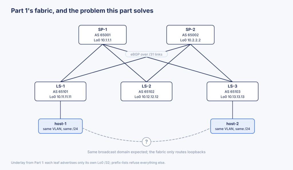
The fabric is the one from Part 1: two spines and three leaves, every switch in its own AS, connected by eBGP over /31 links. The two hosts from the introduction, host-1 on LS-1 and host-2 on LS-3, are the running example for this post. Every section comes back to them and asks what changes for that one conversation.
Why an Overlay at All
There are two ways to connect host-1 and host-2. One is to stretch the VLAN across the spines as a Layer 2 trunk. That brings back spanning tree, blocked links and one shared failure domain, which is what a routed fabric was built to get rid of. The other is to keep the fabric routed and carry the hosts’ Ethernet frames inside IP packets, from one leaf’s loopback to another’s. That second approach is an overlay: a virtual Layer 2 network built on top of a routed one. The routed network underneath, the one we built in Part 1, is the underlay.
An overlay also brings three things a stretched VLAN can’t:
- More segments. An 802.1Q VLAN ID is 12 bits, which leaves 4094 usable VLANs. VXLAN identifies a segment with a 24-bit VXLAN Network Identifier (VNI): about 16 million segments.
- Tenancy. Two tenants can reuse the same MAC and IP addresses, because the VNI, not the address, decides which segment a frame belongs to.
- Mobility. A workload can move to another rack and keep its address, because its subnet is no longer pinned to one leaf.
The overlay doesn’t replace the underlay. It rides on top of it and asks Part 1 for one change: a second loopback on each leaf, from a new 10.255.1.0/24 block, to act as the tunnel endpoint.
In short: Part 1’s fabric routes loopbacks and nothing else, so two hosts in the same subnet on different leaves can’t talk. An overlay carries their Ethernet frames across the routed underlay instead of stretching the VLAN.
VXLAN, the Data Plane
VXLAN (Virtual eXtensible LAN) is the overlay’s data plane: the packet format a leaf uses to carry a host’s frame across the underlay. When host-1 sends a frame to host-2, LS-1 encapsulates the entire Ethernet frame in four new headers and routes the result to LS-3. LS-3 removes those headers (decapsulation) and delivers the original frame to host-2, as if the two hosts shared a switch.
The device that encapsulates and decapsulates is a VXLAN Tunnel End Point (VTEP). On our fabric every leaf is a VTEP, and its tunnel address is Loopback1. The spines are not VTEPs: to them a VXLAN packet is an ordinary IP packet from one leaf loopback to another.
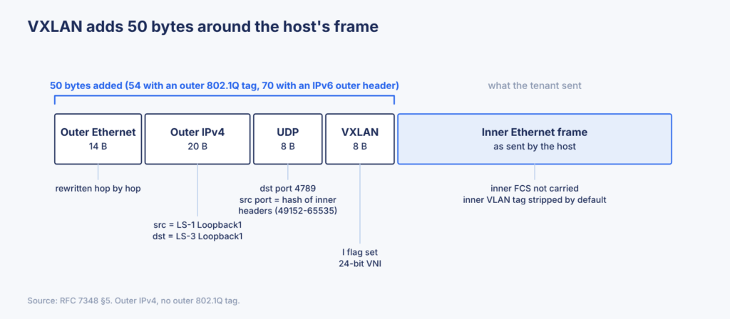
From the outside in:
| Header | Bytes | What it does |
|---|---|---|
| Outer Ethernet | 14 | Gets the packet to the next router; rewritten at every hop like any routed packet |
| Outer IPv4 | 20 | Source is LS-1’s VTEP address, destination is LS-3’s |
| Outer UDP | 8 | Destination port 4789; source port is a hash of the inner headers |
| VXLAN | 8 | A flag that marks the VNI as valid, and the 24-bit VNI itself |
| Inner Ethernet frame | as sent | host-1’s original frame, without its FCS; any inner VLAN tag is normally removed |
The format comes from RFC 7348, which is an Informational RFC published outside the IETF standards process. Its authors include engineers from Arista, Cisco, VMware, Broadcom, Intel and Red Hat, and the format it documents is the one every vendor ships.
The UDP Source Port Is What Makes ECMP Work
Every packet between LS-1 and LS-3 has the same outer source and destination IP. Part 1’s ECMP (maximum-paths 2 on the leaves) chooses a path by hashing packet headers, so if the outer UDP source port were fixed as well, every conversation between the two leaves would hash onto the same spine. RFC 7348 recommends setting the source port from a hash of the inner headers, in the range 49152-65535. Different host conversations get different source ports, so they spread across SP-1 and SP-2. Whether cEOS actually spreads them that way is something to observe in Part 3.
50 Extra Bytes, and No Fragmentation
Add up the outer headers: 14 + 20 + 8 + 8 = 50 bytes over IPv4, 54 if the outer frame carries an 802.1Q tag, 70 with an IPv6 outer header. A host that sends a full 1500-byte packet produces a VXLAN packet 50 bytes larger.
RFC 7348 says VTEPs must not fragment VXLAN packets, and a receiving VTEP may silently drop fragments. So the underlay MTU has to fit the host’s largest frame plus 50 bytes. Arista’s EVPN sample configuration uses 9214 bytes on fabric links and 9164 on the hosts’ gateway interfaces (SVIs), exactly 50 apart. An MTU mismatch looks like an EVPN problem but isn’t one: small packets get through and large ones disappear. Part 3 checks the MTU before anything else.
In short: VXLAN encapsulates the host’s whole Ethernet frame in outer Ethernet, IP, UDP and VXLAN headers, 50 bytes in total, sent from one leaf’s VTEP to another’s. The UDP source port gives ECMP something to hash on, and the underlay MTU has to absorb the extra 50 bytes.
Flood-and-Learn, and Why It Wasn’t Enough
The VXLAN header tells LS-3 what to do with a packet it receives. It says nothing about the harder question: how does LS-1 know that host-2 is behind LS-3 in the first place? RFC 7348’s answer is flood-and-learn: the way an ordinary switch learns MAC addresses, stretched across the underlay.
How Flood-and-Learn Works
Take the first thing host-1 does when it wants to reach host-2: it sends an ARP request, which is a broadcast.
- LS-1 receives the broadcast and has no idea where host-2 is. It encapsulates the frame and sends it to an IP multicast group that is mapped to the VNI by configuration.
- Every VTEP that joined that group receives a copy, LS-3 included.
- LS-3 decapsulates the frame and learns from the outer header: host-1’s MAC sits behind the VTEP whose address is the outer source IP, LS-1.
- The ARP reply from host-2 goes back as ordinary unicast VXLAN, because LS-3 now knows where host-1 is.
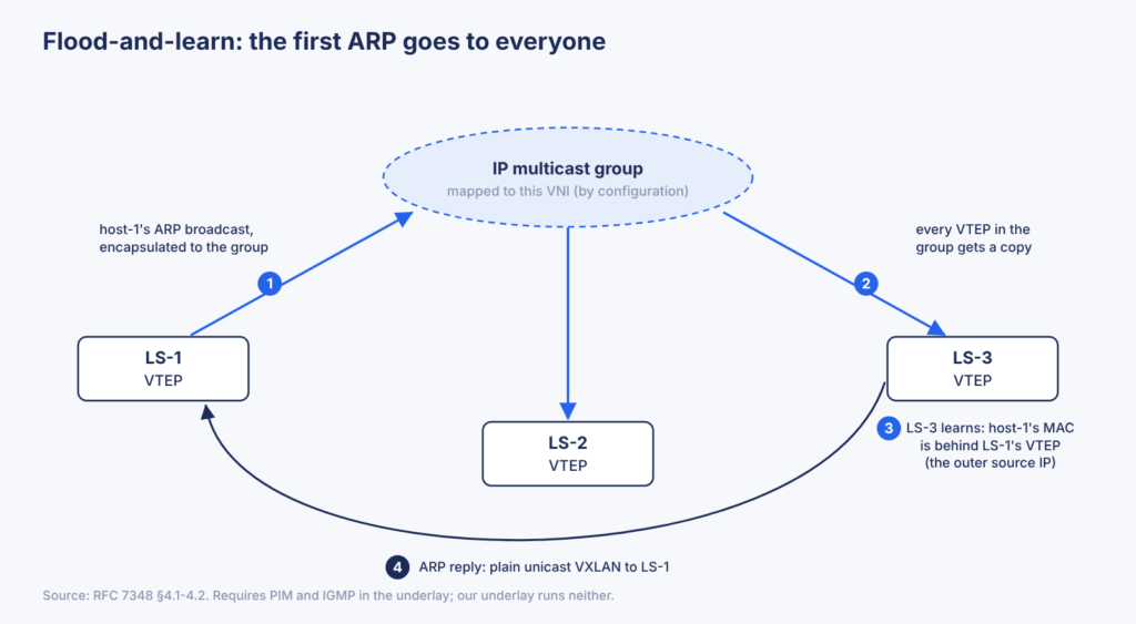
Broadcast, unknown unicast and multicast frames all take that same path to the group. Together they’re called BUM traffic, a term that comes back when EVPN takes over flooding.
Why We’re Not Using It
Multicast delivery needs multicast routing in the underlay: PIM between the switches, IGMP so VTEPs can join groups, and in most PIM designs a rendezvous point. Our underlay runs BGP and nothing else. Flood-and-learn would add a second routing protocol and a multicast design to a fabric we built to be simple.
There is a variant without multicast. Each VTEP keeps a static list of the other VTEPs and sends every BUM frame to each one as a separate unicast copy, which Arista calls head-end replication. It avoids multicast, but every new leaf means editing the list on every other leaf.
Neither version fixes the real limitation: learning is reactive. A VTEP learns a remote MAC only after that host sends something. Until then, traffic to that host floods, a workload that moves is invisible until it speaks, and there’s no way to apply policy to who learns what. RFC 7348 itself names control-plane alternatives and then leaves them out of scope.
In short: Flood-and-learn finds remote MACs by flooding unknown traffic and learning from the outer source IP of what arrives. It needs multicast in the underlay, or flood lists maintained by hand, and it learns only after a host speaks.
EVPN, the Control Plane
Flood-and-learn makes every VTEP discover the network by watching traffic. EVPN turns that around: each leaf announces what it has, and the other leaves learn it from BGP before any data frame needs to be flooded. Which VNIs does LS-3 serve? Which MAC addresses sit behind it? LS-3 tells everyone in a BGP update.
That BGP is the same protocol we ran in Part 1, with the same session setup and the same best-path rules. What changes is the kind of route being carried. EVPN is its own address family in Multiprotocol BGP (AFI 25 for L2VPN, SAFI 70 for EVPN), and two peers exchange EVPN routes only if both advertise that capability when the session comes up. In Part 1 every route was an IPv4 prefix. Here a route can describe a single MAC address.
Following host-1’s MAC
Take the running example: host-1 comes up on LS-1 and sends its first frame.
- LS-1 learns host-1’s MAC on the access port, the way any switch does. Local learning in the data plane still happens.
- LS-1 advertises that MAC to its BGP peers as an EVPN route: this MAC, in this VNI, is reachable through LS-1’s VTEP address, its Loopback1.
- The spines pass the route on to LS-2 and LS-3.
- LS-3 installs it in its MAC table for that VNI: host-1’s MAC, reachable through a VXLAN tunnel to LS-1.
When host-2 later sends a frame to host-1, LS-3 already knows where to encapsulate it. The remote MAC came from the control plane, not from watching traffic. That is the whole idea behind EVPN; the rest of this section covers the details that make step 2 work.
Two terms from the RFCs and vendor documentation are worth knowing here. The per-VNI MAC table on each leaf is called a MAC-VRF. Our leaves are called PEs (provider edge routers), a leftover from EVPN’s origins in MPLS VPNs.
RD and RT: Two Values on Every Route
Every EVPN route carries a Route Distinguisher and a Route Target. Both are written as two numbers separated by a colon, which is why they’re easy to confuse. They answer different questions.
The Route Distinguisher (RD) answers “is this the same route as that one?” It is prepended to the route and becomes part of its identity in the BGP table. When a workload moves between racks, LS-1 and LS-3 can briefly advertise the same MAC. Different RDs keep those as two separate routes, so one advertisement doesn’t silently replace the other. Each MAC-VRF has its own RD, usually built from the leaf’s own IP address plus a number, so every leaf’s RD is different without any planning.
The Route Target (RT) answers “who wants this route?” It is a BGP extended community attached to the route, not part of its identity. Each leaf is configured with the RTs it imports, and a received route enters a MAC-VRF only if it carries one of them. Everything else is ignored.
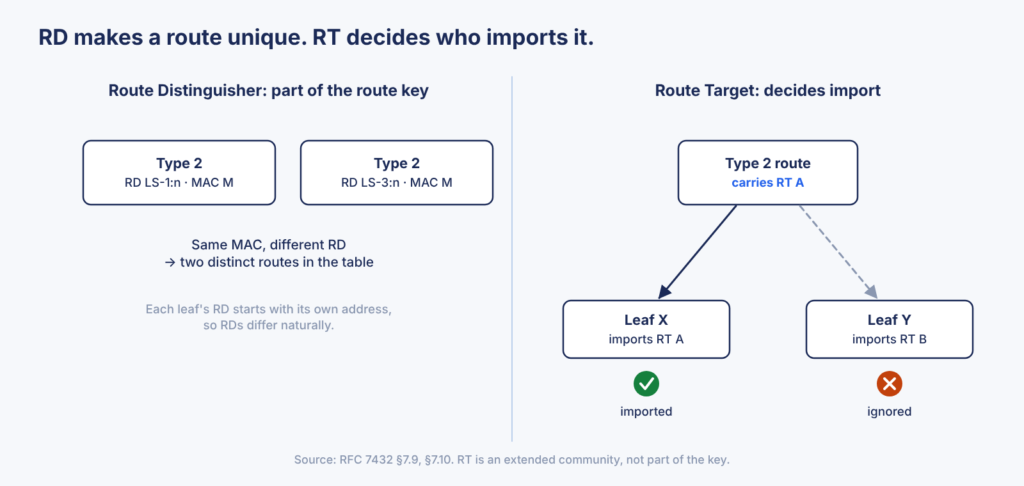
For our fabric, that means RDs take care of themselves, but the RT for a given VNI has to be identical on every leaf, or no leaf imports anything from any other. That sounds trivial. With a different ASN on every switch it isn’t, and Part 3 shows why.
How a Protocol Built for MPLS Carries VXLAN
RFC 7432 defined EVPN for MPLS networks, where every route carries an MPLS label. RFC 8365 reuses the same routes for VXLAN without changing their format. Three details make that work:
- The VNI goes in the label field. The field is three bytes long, enough to carry the full 24-bit VNI.
- An extended community names the encapsulation. The BGP Encapsulation extended community tells the receiving leaf to build a VXLAN tunnel instead of an MPLS path.
- The BGP next hop is the VTEP. RFC 8365 requires the next hop to be the advertising leaf’s VTEP address, our Loopback1. That is the address the receiving leaf will use as the outer destination IP when it encapsulates.
The RT and the encapsulation marking both travel as extended communities. If something along the path strips extended communities, the route still arrives, but it is useless: there is no RT to import it with and no VXLAN marking to build a tunnel from. Keep that in mind for Part 3.
Route Types: Part 3 Needs Two
EVPN defines several route types. They share the address family and differ in what they advertise.
| Type | Name | What it says | Where we use it |
|---|---|---|---|
| 2 | MAC/IP Advertisement | This MAC, and optionally its IP, is behind my VTEP in this VNI | Part 3 (MAC), Part 4 (MAC and IP) |
| 3 | Inclusive Multicast Ethernet Tag | I’m in this VNI; send me its broadcast, unknown unicast and multicast (BUM) traffic this way | Part 3 |
| 5 | IP Prefix | This subnet is reachable through me | Part 4 |
| 1 and 4 | Ethernet Auto-Discovery, Ethernet Segment | Used when one host connects to two leaves (multihoming) | Not in this series yet |
The four steps above were a Type 2 route. Type 3 replaces flood-and-learn’s multicast group, which the replication section below covers. With hosts attached to a single leaf, which is all this series uses for now, Types 2 and 3 carry the control plane.
In short: EVPN is BGP carrying MAC addresses. A leaf advertises each local MAC as a Type 2 route with its own VTEP as the next hop. The RD keeps routes distinct, the RT decides which leaves import them, and extended communities carry both the RT and the VXLAN marking.
Routing Between Subnets
So far host-1 and host-2 share a subnet. Now add host-3, also on LS-3 but in a different subnet. To reach host-3, host-1 sends its packet to its default gateway, and something has to route it. With EVPN, the routing happens on the leaves: each leaf is the default gateway for the hosts attached to it. That’s called Integrated Routing and Bridging (IRB), and RFC 9135 defines two ways to do it. They differ in which leaf does the routing, and that decides how much state every leaf has to hold.
| Asymmetric IRB | Symmetric IRB | |
|---|---|---|
| Ingress leaf (LS-1) | Routes, then bridges | Routes |
| Egress leaf (LS-3) | Bridges only | Routes, then bridges |
| Subnets each leaf must have | All of them, local or not | Only its local ones |
| ARP entries each leaf holds | Local and remote hosts | Local hosts only |
| VNI on the wire | The destination subnet’s VNI | One VNI per tenant for routed traffic |
| TTL decrements across the overlay | 1 | 2 |
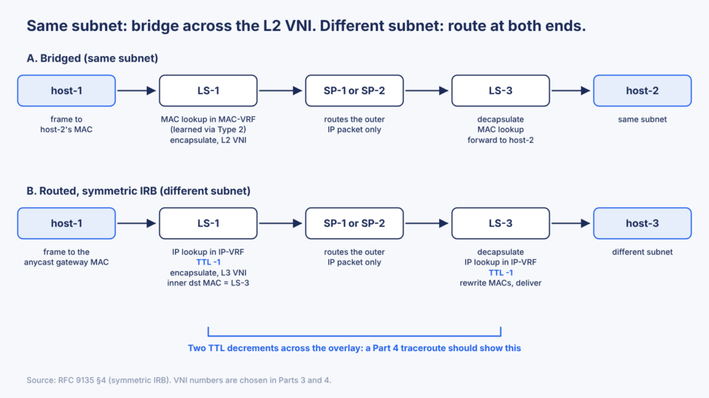
Asymmetric IRB: Route at the Ingress Leaf
LS-1 does all the routing. It routes host-1’s packet into host-3’s subnet, rewrites the inner MAC addresses for host-3, and bridges the result across that subnet’s VNI. LS-3 only bridges. That works only if LS-1 already has host-3’s subnet configured, a gateway interface in it, and an ARP entry for host-3. Repeat that for every leaf and every subnet, and every leaf ends up carrying every subnet, whether it has hosts there or not.
Symmetric IRB: Route at Both Ends
Each tenant gets an IP-VRF, a routing table for that tenant that exists on every leaf, plus one extra VNI used only for routed traffic between leaves: the L3 VNI. (The VNI for a single subnet, the kind we’ve used so far, is the L2 VNI.) LS-1 routes host-1’s packet in the IP-VRF and sends it across the L3 VNI to LS-3. LS-3 routes it again, into host-3’s subnet, and delivers it. Each leaf needs ARP entries only for its own hosts and gateway interfaces only for its own subnets.
Routing at both ends means the TTL drops twice. It also means a Type 2 route carries more than a MAC: the host’s IP address, the L3 VNI next to the L2 VNI, a second RT for the IP-VRF, and an extended community carrying the advertising leaf’s router MAC. LS-1 uses that router MAC as the inner destination MAC when it sends a routed packet to LS-3.
RFC 9135 states the trade-off plainly: symmetric scales better, while asymmetric keeps the control plane simpler and costs nothing extra when every subnet is on every leaf anyway. EOS supports both.
Opinion: I’m going with symmetric IRB for Part 4. A production fabric rarely puts every subnet on every leaf, and I’d rather learn the model that scales than the one that only works while the fabric is small. It also gives me something concrete to verify: two TTL decrements in a traceroute.
One Gateway Address on Every Leaf
If every leaf is a default gateway, a host should see the same gateway wherever it lands. RFC 9135 recommends the simplest way to do that: the same gateway IP and the same gateway MAC on every leaf, known as an anycast gateway. A host that moves to another rack keeps a valid ARP entry for its gateway, and no extra signaling is needed. On EOS, that’s an ip address virtual on each SVI, plus one shared ip virtual-router mac-address.
Type 5 Routes Cover Subnets, Not Just Hosts
Type 2 routes teach each leaf about individual hosts. That leaves a gap: a packet for a host that hasn’t sent anything yet, in a subnet the ingress leaf doesn’t have. RFC 9135 closes it with Type 5 routes, defined in RFC 9136: each leaf also advertises its local subnets as IP prefixes. The first packet then reaches a leaf that does have the subnet, which ARPs for the host, learns it and advertises it as a Type 2. Arista’s examples advertise both route types, and Part 4 builds the same.
In short: With symmetric IRB, every leaf is the anycast gateway for its own subnets and routes between leaves over a per-tenant L3 VNI, so routed traffic is routed twice. Type 2 routes carry hosts, Type 5 routes carry subnets.
Replication and ARP
Flood-and-learn left one problem open: the first ARP from host-1 is a broadcast, and BUM traffic still has to reach every leaf in a VNI. EVPN keeps the flooding but replaces the configuration behind it with routes.
Type 3 Routes Build the Flood List
Every leaf advertises one Type 3 route for each VNI it serves. In effect, the route says “I’m in this VNI; send me its BUM traffic, and here’s how.” The “how” travels in the route’s PMSI Tunnel attribute. On our fabric, it’s ingress replication: the sending leaf makes one unicast copy of the frame for each remote VTEP, and the attribute carries the VTEP address to send it to.
So LS-1’s flood list for a VNI is simply the set of Type 3 routes it has received for that VNI. LS-3 joins the list by advertising one, and nothing on LS-1 changes. It’s flood-and-learn’s head-end replication without the hand-maintained list. Adding an LS-4 later touches only LS-4.
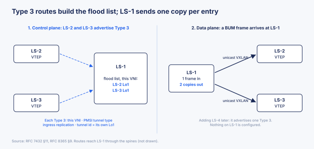
The cost hasn’t disappeared; it has moved to the ingress leaf, which still sends one copy per remote VTEP. With three leaves, that’s two copies, which is nothing. At hundreds of leaves and heavy broadcast rates, it’s the argument for putting multicast back into the underlay. We’re nowhere near that.
ARP Suppression: Answering ARP Locally
ARP is the broadcast every IPv4 host generates, and EVPN can remove much of it. A Type 2 route can carry a host’s IP address next to its MAC. Once LS-1 holds that binding for host-2, RFC 7432 says it should answer host-1’s ARP request itself, as a proxy, instead of flooding it. Vendors call this ARP suppression. On EOS, Type 2 routes with an IP address are what enable it, and ARP flooding into the VXLAN fabric is still on by default.
That gives Part 3 something specific to watch. The first ARP for a host nobody has learned yet still floods to every leaf in the VNI. Once that host’s MAC and IP arrive as a Type 2 route, the next ARP for it can be answered by the local leaf. Whether cEOS does that with its default configuration is something to observe, not assume.
In short: Each leaf advertises a Type 3 route per VNI, and the Type 3 routes a leaf receives become its flood list for ingress replication. Type 2 routes that carry IP addresses let a leaf answer ARP locally instead of flooding it.
What’s Next
Everything so far is standard EVPN. Part 3 builds the Layer 2 half of it on Part 1’s fabric: host-1 and host-2 in one VNI, bridged from LS-1 to LS-3.
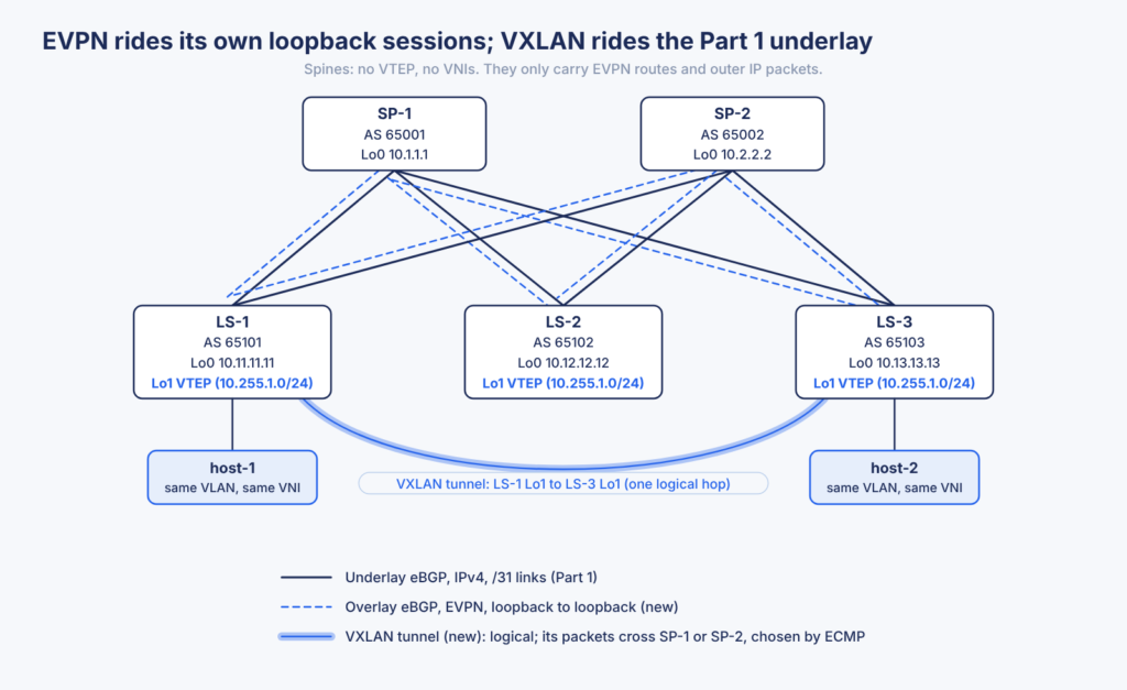
The underlay stays as it is, and three things are added. Each leaf gets a Loopback1 from 10.255.1.0/24 as its VTEP address, which Part 1’s prefix-lists will have to allow. EVPN runs on its own BGP sessions between loopbacks, separate from the /31 underlay sessions, which is the design Arista documents. And each VNI gets one route target that every leaf shares.
Part 1 made two choices most EVPN material doesn’t assume: eBGP everywhere, and a different ASN on every switch. Both bend the theory above in a few places, and most of those bends share one unpleasant trait: the BGP sessions stay up and nothing works. Part 3 takes them one at a time, with the lab output to show each one.
References
- RFC 7348, Virtual eXtensible Local Area Network (VXLAN), RFC Editor, 2014 (link)
- RFC 7432, BGP MPLS-Based Ethernet VPN, IETF, 2015 (link)
- RFC 8365, A Network Virtualization Overlay Solution Using Ethernet VPN (EVPN), IETF, 2018 (link)
- RFC 9135, Integrated Routing and Bridging in Ethernet VPN (EVPN), IETF, 2021 (link)
- RFC 9136, IP Prefix Advertisement in Ethernet VPN (EVPN), IETF, 2021 (link)
- Arista EOS 4.36.2F User Manual: EVPN Overview, Configuring EVPN, Sample Configurations, Arista Networks