Introduction
A leaf-spine fabric is built around a simple idea: every leaf connects to every spine, creating multiple Layer 3 paths between devices at the edge of the fabric. Rather than relying on a traditional access, distribution, and core hierarchy, traffic moving between leaves crosses a spine and can use any available path that the routing system considers valid.
For that topology to work, the fabric first needs an underlay: the routed IP network that provides reachability between its infrastructure endpoints. The underlay includes the point-to-point links between leaves and spines, the addressing assigned to those links, and the routing protocol responsible for exchanging reachability information.
Several routing protocols can fill that role. OSPF and IS-IS are common options, but BGP can also be used as the routing protocol for the fabric itself. In an eBGP underlay, directly connected leaves and spines establish external BGP sessions across their routed links and exchange the prefixes required to make the fabric reachable. This approach has been documented and deployed in Clos-based network designs across multiple vendors and implementations.
In this lab, we will build a small Layer 3 leaf-spine fabric using eBGP as the underlay routing protocol. Each switch will operate in its own autonomous system, every leaf will peer with both spines, and /31 point-to-point networks will provide the directly connected transport between BGP neighbors.
The goal is not simply to make the BGP sessions come up. We will use the resulting fabric to examine how routes propagate from one leaf to another, how multiple paths appear through the spine layer, how those paths are installed for forwarding, and what happens when one of the available links is removed. We will also apply import and export routing policy to explicitly control which infrastructure prefixes are exchanged through the underlay and verify that the expected routes are being accepted and advertised.
By the end, we should have a routed fabric in which BGP provides both reachability and multiple forwarding paths between the nodes, giving us a practical environment for understanding how an eBGP underlay actually behaves.
Learning Objectives
This lab focuses on:
- Understanding the role of an IP underlay in a leaf-spine fabric.
- Examining how traffic moves through a Layer 3 leaf-spine topology.
- Understanding why eBGP can be used as an underlay routing protocol.
- Building eBGP adjacencies between directly connected leaves and spines.
- Advertising and verifying loopback reachability across the fabric.
- Applying import and export routing policy to control the prefixes exchanged through the underlay.
- Verifying that the expected prefixes are being accepted and advertised by those policies.
- Identifying multiple BGP paths and examining how ECMP uses them for forwarding.
- Tracing a prefix as it propagates through the fabric.
- Observing how the underlay responds when a leaf-spine path fails.
What Is an Underlay?
The underlay is the routed IP network that provides connectivity between the devices that make up a fabric. In a Layer 3 leaf-spine design, it is formed by the routed links between leaves and spines, the addressing assigned to those links, and the routing protocol used to exchange reachability information.
Its responsibility is deliberately narrow: provide reliable IP transport between infrastructure endpoints.
A leaf does not need a direct physical connection to every other leaf. Instead, the underlay allows it to learn how to reach remote addresses through the spine layer. As routes are exchanged, each device builds the forwarding information needed to move packets across the fabric.
In our lab, eBGP will provide that routing information. The leaf-spine links themselves give directly connected neighbors enough reachability to establish their BGP sessions. BGP will then advertise the loopback prefixes that need to be reachable beyond those local links.
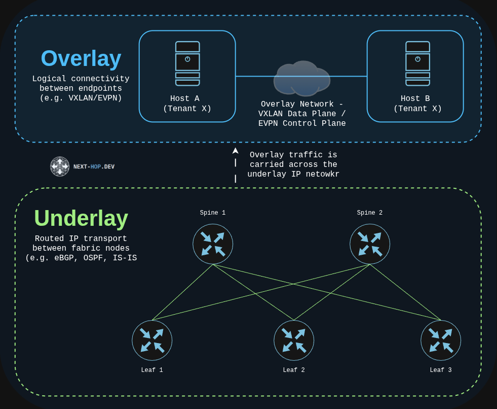
The distinction becomes especially useful when technologies such as VXLAN and EVPN are introduced. An overlay can create logical connectivity between endpoints, but the packets carrying that overlay still depend on the underlying IP fabric to reach their destination. The underlay does not need to understand the logical network being transported; it only needs to know how to reach the infrastructure endpoint at the other side. Cisco describes this role in EVPN/VXLAN fabrics primarily in terms of providing reachability for VTEP and BGP peering addresses.
For this lab, however, there is no overlay. That separation is useful because it lets us examine the routed fabric on its own: how neighbors establish reachability, how prefixes move through the topology, and how multiple paths become available between nodes.
Why Spine-Leaf?
A spine-leaf topology is a folded Clos design built from two physical switch tiers: leaves and spines. Leaf switches sit at the edge of the fabric and provide connectivity to endpoints or other network services, while spine switches provide the transit path between leaves.
The defining relationship is simple: every leaf connects to every spine. Leaves do not need direct links to one another, and spines typically do not connect directly to other spines within the same fabric. When traffic moves from one leaf to another, it crosses one of the available spines.
This creates a consistent forwarding structure. Rather than different parts of the network depending on different hierarchical paths, traffic between leaves follows the same basic pattern: ingress leaf, spine, egress leaf. More importantly for our lab, connecting each leaf to multiple spines creates multiple Layer 3 paths toward the same destination.
Those parallel paths are where Equal-Cost Multipath (ECMP) becomes important. When the routing protocol provides multiple equally preferred paths and the platform supports installing them, traffic can be forwarded across more than one next hop instead of relying on a single active path. ECMP is therefore closely tied to how a routed Clos fabric makes use of its available links.
The topology also provides redundancy naturally. If a leaf has connectivity through multiple spines, losing one leaf-spine link does not necessarily isolate that leaf; another routed path can remain available through a different spine. In a properly designed fabric, the routing system reacts to the failed path and continues forwarding over the paths that remain.
Spine-leaf is also a scale-out architecture. Additional leaves can expand connectivity at the edge, while spine capacity determines how much connectivity and bandwidth is available between those leaves. The resulting fabric is not automatically non-blocking, however. Port counts, link speeds, and oversubscription all influence how much traffic the fabric can actually carry.
Why eBGP for the Underlay?
OSPF, IS-IS, and BGP can all provide routing for a Layer 3 leaf-spine fabric. For this lab, the underlay will use external BGP (eBGP), with each routed leaf-spine connection forming a single-hop BGP adjacency between devices in different autonomous systems.
This model maps cleanly to the physical topology. Each leaf and spine is already connected by a point-to-point Layer 3 link, so the addresses on those links provide the directly connected reachability needed to establish the BGP sessions. No separate IGP is required to resolve the BGP neighbors. RFC 7938 documents this same general approach for Clos fabrics, using single-hop eBGP sessions across the direct point-to-point links between network nodes.
BGP also provides useful control over which routing information is allowed to enter and leave the fabric. Import and export policy can be applied at BGP boundaries so that the routes exchanged through the underlay reflect the intended design rather than simply accepting or advertising every available prefix. In this lab, that will allow the infrastructure prefixes required by the fabric to be explicitly permitted and verified. This same principle appears in automated fabric systems such as Juniper Apstra, which generates routing policies controlling route import and export as part of the fabric design.
Another useful property is the visibility provided by BGP itself. Routes can be examined as they are received from a neighbor, evaluated by policy, selected by BGP, installed into the routing table, and advertised onward to another peer. The AS_PATH also provides a record of the autonomous systems a route has traversed while supplying BGP’s built-in inter-AS loop prevention. This makes it possible to follow a prefix through the fabric and understand not only where it was learned, but how it reached the local device.
The ASN design is also flexible. Some fabrics reuse ASNs at particular tiers, while others assign a unique ASN to every node. For this lab, each spine and leaf will use its own private ASN. This keeps the autonomous-system boundaries obvious and makes the resulting AS_PATH straightforward to examine as routes move between leaves through the spine layer. Unique per-device ASNs are also used in documented IP-fabric reference designs, although they are not a requirement for an eBGP underlay.
Finally, eBGP works well with the multiple paths provided by the leaf-spine topology. A leaf can learn the same remote prefix through more than one spine, and when the relevant path attributes are equally preferred, BGP multipath can allow those routes to participate in ECMP forwarding. On Arista EOS, this behavior will become particularly important because the two paths can contain different spine ASNs while still having the same AS-path length.
The result is an underlay with a relatively simple division of responsibility: the physical links provide direct connectivity, eBGP exchanges reachability, routing policy controls what is exchanged, and ECMP makes use of the redundant paths provided by the topology.
Lab Topology and Addressing
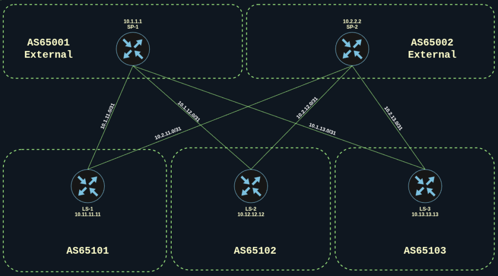
The lab uses a five-node Layer 3 leaf-spine topology consisting of two spines and three leaves. Every leaf has a routed connection to both spines, providing two possible paths through the fabric.
| Device | Role | ASN | Loopback0 |
|---|---|---|---|
| SP-1 | Spine | 65001 | 10.1.1.1/32 |
| SP-2 | Spine | 65002 | 10.2.2.2/32 |
| LS-1 | Leaf | 65101 | 10.11.11.11/32 |
| LS-2 | Leaf | 65102 | 10.12.12.12/32 |
| LS-3 | Leaf | 65103 | 10.13.13.13/32 |
A unique ASN on every switch is a design choice for this lab rather than a requirement of an eBGP underlay. It keeps each BGP boundary explicit and will make the AS_PATH easy to follow as prefixes move from one leaf, through a spine, and toward another leaf.
Each leaf-spine connection uses its own /31 network:
| Connection | Point-to-Point Network |
|---|---|
| SP-1 ↔ LS-1 | 10.1.11.0/31 |
| SP-1 ↔ LS-2 | 10.1.12.0/31 |
| SP-1 ↔ LS-3 | 10.1.13.0/31 |
| SP-2 ↔ LS-1 | 10.2.11.0/31 |
| SP-2 ↔ LS-2 | 10.2.12.0/31 |
| SP-2 ↔ LS-3 | 10.2.13.0/31 |
A /31 is well suited to these links because a point-to-point connection only requires addresses for its two endpoints. RFC 3021 allows both addresses in the subnet to be used for that purpose, avoiding the additional network and broadcast addresses associated with a traditional /30.
The addressing pattern is also intentionally easy to associate with the topology. The first variable octet identifies the spine and the next identifies the leaf: 10.1.12.0/31, for example, is the connection between SP-1 and LS-2, while 10.2.13.0/31 identifies the SP-2 to LS-3 link.
The loopbacks serve a different purpose from the transit links. Each provides a stable /32 infrastructure address for its switch that is not tied to any single physical leaf-spine connection. These are the prefixes that will be advertised through the underlay and used later to examine route propagation, path selection, ECMP, and failure behavior.
Expected Routing Behavior
Before configuring BGP, it is useful to establish what the finished control plane should look like. This creates a baseline for the verification steps later in the lab and makes it easier to determine whether the observed behavior matches the design.
Each leaf has a direct Layer 3 connection to both spines and should therefore establish two eBGP sessions. Each spine connects to all three leaves and should establish three eBGP sessions. There are no direct BGP sessions between leaves or between the two spines.
Once the loopbacks are advertised, a prefix originating from one leaf should be able to reach another leaf through either spine. For example, LS-1 will originate 10.11.11.11/32. Both SP-1 and SP-2 should learn that prefix directly from AS65101 and advertise it toward LS-2.
From LS-2, the same destination should therefore be visible through two paths:
| Path | Expected AS_PATH |
|---|---|
| Through SP-1 | 65001 65101 |
| Through SP-2 | 65002 65101 |
The AS_PATH contents are different because each route crosses a different spine ASN, but both paths have the same AS-path length. With the remaining relevant BGP attributes equal and multipath enabled, both routes can participate in ECMP forwarding.
The topology should also provide predictable behavior during a single link failure. If one of a leaf’s spine connections is lost, the BGP session across that link should go down and the associated path should be removed. Reachability should remain through the surviving spine until the failed link and BGP adjacency return.
| Behavior | Expected Result |
|---|---|
| Leaf BGP neighbors | 2 established sessions |
| Spine BGP neighbors | 3 established sessions |
| Remote leaf loopback | Learned through both spines |
| AS_PATH | Different spine ASN, equal path length |
| ECMP | Two forwarding paths when multipath is enabled |
| Single leaf-spine link failure | One path removed while reachability remains |
| Link restoration | Second path returns |
This gives us a clear set of expectations to compare against the actual EOS control-plane and forwarding output once the fabric is configured.
Building the Fabric with netlab
Rather than manually creating five cEOS nodes and configuring every routed interface individually, this lab uses netlab with containerlab to build the base fabric. The topology, addressing, loopbacks, and BGP autonomous systems are described in a topology.yml file, which netlab then translates into the underlying containerlab topology and EOS configuration.
The lab uses Arista cEOS 4.36.2 and enables netlab’s BGP configuration module globally. Each node is assigned its own loopback address and private ASN, while the six leaf-spine connections are defined explicitly using the /31 networks from the addressing plan.
Topology.yml
---
name: ebgp-underlay

provider: clab

defaults:
  device: eos
  devices:
    eos:
      clab:
        image: "ceos:4.36.2"

module: [ bgp ]

nodes:
  SP-1:
    loopback.ipv4: 10.1.1.1/32
    bgp.as: 65001

  SP-2:
    loopback.ipv4: 10.2.2.2/32
    bgp.as: 65002

  LS-1:
    loopback.ipv4: 10.11.11.11/32
    bgp.as: 65101

  LS-2:
    loopback.ipv4: 10.12.12.12/32
    bgp.as: 65102

  LS-3:
    loopback.ipv4: 10.13.13.13/32
    bgp.as: 65103

links:
  - name: SP-1 to LS-1
    interfaces: [ SP-1, LS-1 ]
    prefix:
      ipv4: 10.1.11.0/31
      allocation: sequential

  - name: SP-1 to LS-2
    interfaces: [ SP-1, LS-2 ]
    prefix:
      ipv4: 10.1.12.0/31
      allocation: sequential

  - name: SP-1 to LS-3
    interfaces: [ SP-1, LS-3 ]
    prefix:
      ipv4: 10.1.13.0/31
      allocation: sequential

  - name: SP-2 to LS-1
    interfaces: [ SP-2, LS-1 ]
    prefix:
      ipv4: 10.2.11.0/31
      allocation: sequential

  - name: SP-2 to LS-2
    interfaces: [ SP-2, LS-2 ]
    prefix:
      ipv4: 10.2.12.0/31
      allocation: sequential

  - name: SP-2 to LS-3
    interfaces: [ SP-2, LS-3 ]
    prefix:
      ipv4: 10.2.13.0/31
allocation: sequentialThe ordering of the interfaces on each link is intentional. With sequential address allocation, netlab assigns addresses according to their position in the link definition. Listing the spine first results in the lower address being assigned to the spine and the higher address to the leaf. In this lab, that produces the .0 spine and .1 leaf convention across all six /31 links.
Enabling the BGP module also removes much of the repetitive neighbor configuration. When directly connected devices use different autonomous systems, netlab automatically creates a single-hop eBGP session between their interface addresses. The module also advertises each node’s default loopback into BGP unless that behavior is explicitly disabled.
Before starting any containers, netlab can build the transformed topology and show exactly what it plans to configure. A typo in topology.yml is much cheaper to catch here than in a running fabric.
netlab create

netlab inspect --node SP-1 interfaces
netlab inspect --node LS-1 bgpThe interface view for SP-1 shows Ethernet1 through Ethernet3 facing LS-1, LS-2 and LS-3, each with the .0 address from its /31:
%YAML 1.1
---
- ipv4: 10.1.11.0/31
  name: SP-1 to LS-1
  linkindex: 1
  role: external
  type: p2p
  ifindex: 1
  ifname: Ethernet1
  mac_address: caf0.0001.0001
  clab:
    name: et1
  neighbors:
  - ipv4: 10.1.11.1/31
    ifname: Ethernet1
    node: LS-1
- ipv4: 10.1.12.0/31
  name: SP-1 to LS-2
  linkindex: 2
  role: external
  type: p2p
  ifindex: 2
  ifname: Ethernet2
  mac_address: caf0.0001.0002
  clab:
    name: et2
  neighbors:
  - ipv4: 10.1.12.1/31
    ifname: Ethernet1
    node: LS-2
- ipv4: 10.1.13.0/31
  name: SP-1 to LS-3
  linkindex: 3
  role: external
  type: p2p
  ifindex: 3
  ifname: Ethernet3
  mac_address: caf0.0001.0003
  clab:
    name: et3
  neighbors:
  - ipv4: 10.1.13.1/31
    ifname: Ethernet1
node: LS-3The BGP view for LS-1 shows it in AS65101 with two eBGP neighbors, SP-1 at 10.1.11.0 and SP-2 at 10.2.11.0, and its 10.11.11.11/32 loopback lined up for advertisement:
%YAML 1.1
---
advertise_loopback: true
community:
  ibgp:
  - standard
  - large
  - extended
  ebgp:
  - standard
  - large
  localas_ibgp:
  - standard
  - large
  - extended
next_hop_self: true
_cprop_order:
- standard
- extended
- large
- link-bandwidth
as: 65101
router_id: 10.11.11.11
neighbors:
- ifindex: 1
  name: SP-1
  as: 65001
  type: ebgp
  ipv4: 10.1.11.0
  activate:
    ipv4: true
- ifindex: 2
  name: SP-2
  as: 65002
  type: ebgp
  ipv4: 10.2.11.0
  activate:
    ipv4: true
ipv4: true
advertise:
- ipv4: 10.11.11.11/32 Once the transformed topology matches the intended design, the lab can be started and the generated configuration deployed with:
netlab upAt that point the declarative topology has been translated into a running five-node cEOS fabric. Before trusting it, it’s worth checking what EOS actually received from netlab.
Examining the Generated EOS Configuration
The transformed topology describes what netlab intends to build, but the running configuration confirms how that intent was translated into EOS. Rather than reviewing all five devices, one spine and one leaf provide enough detail to see the configuration pattern used throughout the fabric.
On SP-1, netlab converted the three leaf-facing interfaces into routed ports and assigned the expected .0 address from each /31. Loopback0 was also configured with the infrastructure address defined in topology.yml.
interface Ethernet1
   description SP-1 to LS-1 [external]
   no switchport
   ip address 10.1.11.0/31

interface Ethernet2
   description SP-1 to LS-2 [external]
   no switchport
   ip address 10.1.12.0/31

interface Ethernet3
   description SP-1 to LS-3 [external]
   no switchport
   ip address 10.1.13.0/31

interface Loopback0
   ip address 10.1.1.1/32

ip routingThe BGP process also reflects the topology definition. SP-1 operates in AS65001, uses its loopback as the BGP router ID, and establishes an eBGP relationship with each leaf. The network statement originates the SP-1 loopback into BGP.
router bgp 65001
   router-id 10.1.1.1
   no bgp default ipv4-unicast
   bgp advertise-inactive

   neighbor 10.1.11.1 remote-as 65101
   neighbor 10.1.11.1 description LS-1

   neighbor 10.1.12.1 remote-as 65102
   neighbor 10.1.12.1 description LS-2

   neighbor 10.1.13.1 remote-as 65103
   neighbor 10.1.13.1 description LS-3

   address-family ipv4
      neighbor 10.1.11.1 activate
      neighbor 10.1.11.1 next-hop-self
      neighbor 10.1.12.1 activate
      neighbor 10.1.12.1 next-hop-self
      neighbor 10.1.13.1 activate
      neighbor 10.1.13.1 next-hop-self
network 10.1.1.1/32The leaf configuration follows the same pattern with two routed uplinks instead of three. LS-1 uses the .1 address on both point-to-point links, operates in AS65101, and forms separate eBGP sessions with SP-1 and SP-2.
interface Ethernet1
   description SP-1 to LS-1 [external]
   no switchport
   ip address 10.1.11.1/31

interface Ethernet2
   description SP-2 to LS-1 [external]
   no switchport
   ip address 10.2.11.1/31

interface Loopback0
   ip address 10.11.11.11/32

ip routing

router bgp 65101
   router-id 10.11.11.11
   no bgp default ipv4-unicast
   bgp advertise-inactive

   neighbor 10.1.11.0 remote-as 65001
   neighbor 10.1.11.0 description SP-1

   neighbor 10.2.11.0 remote-as 65002
   neighbor 10.2.11.0 description SP-2

   address-family ipv4
      neighbor 10.1.11.0 activate
      neighbor 10.1.11.0 next-hop-self
      neighbor 10.2.11.0 activate
      neighbor 10.2.11.0 next-hop-self
network 10.11.11.11/32The remaining devices follow the same structure with their respective addresses and ASNs. At this point, the base underlay configuration is in place. The next step is to verify whether the BGP adjacencies and learned prefixes actually match the behavior predicted earlier.
Verifying the BGP Sessions
With the base configuration in place, the first verification step is to confirm that the eBGP adjacencies match the fabric design. Both SP-1 and SP-2 are expected to establish one session with each of the three leaves, giving each spine three eBGP neighbors. Each leaf connects to both spines and is therefore expected to maintain two eBGP neighbors.
Rather than repeat nearly identical output from every device, SP-1 and LS-1 provide representative views from each role in the fabric.
On SP-1, show ip bgp summary confirms three established sessions, one toward each leaf:
SP-1#show ip bgp summary
BGP summary information for VRF default
Router identifier 10.1.1.1, local AS number 65001

Description  Neighbor   V AS     Up/Down   State  PfxRcd PfxAcc PfxAdv
LS-1         10.1.11.1  4 65101  00:19:10  Estab  2      2      3
LS-2         10.1.12.1  4 65102  00:19:10  Estab  2      2      4
LS-3 10.1.13.1 4 65103 00:19:10 Estab 2 2 4All three neighbors are in the Established state. The remote ASNs also match the intended design: AS65101 for LS-1, AS65102 for LS-2, and AS65103 for LS-3. SP-2 follows the same pattern, maintaining its own eBGP session with each of the three leaves.
From the leaf side, LS-1 shows the opposite relationship. It maintains one session with each spine:
LS-1#show ip bgp summary
BGP summary information for VRF default
Router identifier 10.11.11.11, local AS number 65101

Description  Neighbor   V AS     Up/Down   State  PfxRcd PfxAcc PfxAdv
SP-1         10.1.11.0  4 65001  00:19:17  Estab  3      3      2
SP-2 10.2.11.0 4 65002 00:19:16 Estab 3 3 4Both sessions are established, confirming that LS-1 has connectivity into the fabric through SP-1 and SP-2. LS-2 and LS-3 follow the same two-neighbor pattern.
The BGP control plane now matches the topology: each spine peers with all three leaves, and each leaf peers with both spines. With the adjacencies established, the next step is to examine how a prefix originating on one leaf propagates through both spines and reaches another leaf.
Following a Prefix Through the Fabric
With the eBGP adjacencies established, the next step is to examine how a prefix moves between leaves. The LS-2 loopback, 10.12.12.12/32, provides a useful example because LS-2 advertises the prefix toward both spines, giving LS-1 two possible paths to the same destination.
A targeted lookup from LS-1 shows both paths in the BGP table:
LS-1#show ip bgp 10.12.12.12/32
BGP routing table information for VRF default
Router identifier 10.11.11.11, local AS number 65101
BGP routing table entry for 10.12.12.12/32
 Paths: 2 available

  65001 65102
    10.1.11.0 from 10.1.11.0 (10.1.1.1)
      Origin IGP, metric 0, localpref 100, IGP metric 0, weight 0, tag 0
      Received 00:20:20 ago, valid, external, best
      Rx SAFI: Unicast

  65002 65102
    10.2.11.0 from 10.2.11.0 (10.2.2.2)
      Origin IGP, metric 0, localpref 100, IGP metric 0, weight 0, tag 0
      Received 00:20:20 ago, valid, external
Rx SAFI: UnicastBoth entries describe a valid path to the same LS-2 loopback, but they arrived through different spines. The AS_PATH makes that distinction visible:
| Path | Next Hop | AS_PATH |
|---|---|---|
| Through SP-1 | 10.1.11.0 | 65001 65102 |
| Through SP-2 | 10.2.11.0 | 65002 65102 |
The first path was advertised by SP-1 in AS65001 after learning the prefix from LS-2 in AS65102. The second followed the same process through SP-2 in AS65002. Both paths therefore have an AS_PATH length of two even though the actual ASNs differ.
At this stage, both paths exist in the BGP control plane, but only the route through SP-1 is marked as the best path. The routing table confirms that only that next hop is currently being used for forwarding:
LS-1#show ip route 10.12.12.12/32

VRF: default

 B E      10.12.12.12/32 [200/0]
via 10.1.11.0, Ethernet1This distinction is important: learning multiple BGP paths does not automatically mean that all of them are installed for forwarding. EOS defaults to one BGP parallel path. Although bgp bestpath as-path multipath-relax is enabled by default and allows equal-length AS paths containing different ASNs to qualify for multipath, maximum-paths must still be configured before multiple BGP routes can participate in ECMP.
For now, the fabric has two valid control-plane paths between LS-1 and LS-2 but only one active forwarding path. That gives us a useful baseline before routing policy and ECMP are introduced.
Controlling Underlay Route Exchange
Establishing the BGP sessions gives the fabric reachability, but it also raises another design question: which routes should each device actually be allowed to accept and advertise?
Before adding routing policy, SP-1 was learning SP-2’s loopback indirectly through all three leaves:
Network         Next Hop     AS_PATH
10.2.2.2/32     10.1.11.1    65101 65002
10.2.2.2/32     10.1.12.1    65102 65002
10.2.2.2/32 10.1.13.1 65103 65002Those routes are valid from BGP’s perspective, but they are unnecessary for this design. Each leaf learned the SP-2 loopback and then advertised it back toward SP-1, effectively allowing the leaves to act as transit between the two spines.
The intended underlay is simpler. Leaves advertise their own loopback prefixes, while the spines provide transit for those leaf prefixes across the fabric. The /31 point-to-point networks remain local to each link and are not advertised into BGP. RFC 7938 describes this as a valid approach for eBGP Clos fabrics because remote devices do not require reachability to every point-to-point subnet.
Import and export policy can enforce that routing intent. On EOS, prefix-lists define the permitted prefixes and route-maps apply those lists to BGP neighbors in the inbound and outbound directions.
Applying the Underlay Routing Policy
The policy is applied across all five switches. The spines accept the expected leaf loopbacks and advertise their own loopback along with the leaf prefixes they have learned. The leaves accept the expected fabric loopbacks but advertise only their own locally originated Loopback0 prefix.
The complete policy configuration used in the lab is shown below
### SP-1 ###

configure terminal

ip prefix-list PL-UNDERLAY-IN
   seq 10 permit 10.11.11.11/32
   seq 20 permit 10.12.12.12/32
   seq 30 permit 10.13.13.13/32

ip prefix-list PL-UNDERLAY-OUT
   seq 10 permit 10.1.1.1/32
   seq 20 permit 10.11.11.11/32
   seq 30 permit 10.12.12.12/32
   seq 40 permit 10.13.13.13/32

route-map RM-UNDERLAY-IN permit 10
   match ip address prefix-list PL-UNDERLAY-IN

route-map RM-UNDERLAY-OUT permit 10
   match ip address prefix-list PL-UNDERLAY-OUT

router bgp 65001
   address-family ipv4
      neighbor 10.1.11.1 route-map RM-UNDERLAY-IN in
      neighbor 10.1.11.1 route-map RM-UNDERLAY-OUT out
      neighbor 10.1.12.1 route-map RM-UNDERLAY-IN in
      neighbor 10.1.12.1 route-map RM-UNDERLAY-OUT out
      neighbor 10.1.13.1 route-map RM-UNDERLAY-IN in
      neighbor 10.1.13.1 route-map RM-UNDERLAY-OUT out

end

### SP-2 ###

configure terminal

ip prefix-list PL-UNDERLAY-IN
   seq 10 permit 10.11.11.11/32
   seq 20 permit 10.12.12.12/32
   seq 30 permit 10.13.13.13/32

ip prefix-list PL-UNDERLAY-OUT
   seq 10 permit 10.2.2.2/32
   seq 20 permit 10.11.11.11/32
   seq 30 permit 10.12.12.12/32
   seq 40 permit 10.13.13.13/32

route-map RM-UNDERLAY-IN permit 10
   match ip address prefix-list PL-UNDERLAY-IN

route-map RM-UNDERLAY-OUT permit 10
   match ip address prefix-list PL-UNDERLAY-OUT

router bgp 65002
   address-family ipv4
      neighbor 10.2.11.1 route-map RM-UNDERLAY-IN in
      neighbor 10.2.11.1 route-map RM-UNDERLAY-OUT out
      neighbor 10.2.12.1 route-map RM-UNDERLAY-IN in
      neighbor 10.2.12.1 route-map RM-UNDERLAY-OUT out
      neighbor 10.2.13.1 route-map RM-UNDERLAY-IN in
      neighbor 10.2.13.1 route-map RM-UNDERLAY-OUT out

end

### LS-1 ###

configure terminal

ip prefix-list PL-UNDERLAY-IN
   seq 10 permit 10.1.1.1/32
   seq 20 permit 10.2.2.2/32
   seq 30 permit 10.12.12.12/32
   seq 40 permit 10.13.13.13/32

ip prefix-list PL-UNDERLAY-OUT
   seq 10 permit 10.11.11.11/32

route-map RM-UNDERLAY-IN permit 10
   match ip address prefix-list PL-UNDERLAY-IN

route-map RM-UNDERLAY-OUT permit 10
   match ip address prefix-list PL-UNDERLAY-OUT

router bgp 65101
   address-family ipv4
      neighbor 10.1.11.0 route-map RM-UNDERLAY-IN in
      neighbor 10.1.11.0 route-map RM-UNDERLAY-OUT out
      neighbor 10.2.11.0 route-map RM-UNDERLAY-IN in
      neighbor 10.2.11.0 route-map RM-UNDERLAY-OUT out

end

### LS-2 ###

configure terminal

ip prefix-list PL-UNDERLAY-IN
   seq 10 permit 10.1.1.1/32
   seq 20 permit 10.2.2.2/32
   seq 30 permit 10.11.11.11/32
   seq 40 permit 10.13.13.13/32

ip prefix-list PL-UNDERLAY-OUT
   seq 10 permit 10.12.12.12/32

route-map RM-UNDERLAY-IN permit 10
   match ip address prefix-list PL-UNDERLAY-IN

route-map RM-UNDERLAY-OUT permit 10
   match ip address prefix-list PL-UNDERLAY-OUT

router bgp 65102
   address-family ipv4
      neighbor 10.1.12.0 route-map RM-UNDERLAY-IN in
      neighbor 10.1.12.0 route-map RM-UNDERLAY-OUT out
      neighbor 10.2.12.0 route-map RM-UNDERLAY-IN in
      neighbor 10.2.12.0 route-map RM-UNDERLAY-OUT out

end


### LS-3 ###

configure terminal

ip prefix-list PL-UNDERLAY-IN
   seq 10 permit 10.1.1.1/32
   seq 20 permit 10.2.2.2/32
   seq 30 permit 10.11.11.11/32
   seq 40 permit 10.12.12.12/32

ip prefix-list PL-UNDERLAY-OUT
   seq 10 permit 10.13.13.13/32

route-map RM-UNDERLAY-IN permit 10
   match ip address prefix-list PL-UNDERLAY-IN

route-map RM-UNDERLAY-OUT permit 10
   match ip address prefix-list PL-UNDERLAY-OUT

router bgp 65103
   address-family ipv4
      neighbor 10.1.13.0 route-map RM-UNDERLAY-IN in
      neighbor 10.1.13.0 route-map RM-UNDERLAY-OUT out
      neighbor 10.2.13.0 route-map RM-UNDERLAY-IN in
      neighbor 10.2.13.0 route-map RM-UNDERLAY-OUT out

endAfter the policy was applied across the fabric, the BGP routes were reprocessed with a soft reset so the existing sessions could remain established while the new import and export policies took effect:
clear ip bgp * softVerifying the Routing Policy
The first check is SP-1’s BGP table. Before policy was applied, SP-1 learned the SP-2 loopback indirectly through all three leaves. After policy, those paths are gone. SP-1 now contains only its locally originated loopback and the three leaf loopbacks it is expected to learn:
SP-1#show ip bgp

Network          Next Hop     Path
10.1.1.1/32      -            i
10.11.11.11/32   10.1.11.1    65101 i
10.12.12.12/32   10.1.12.1    65102 i
10.13.13.13/32 10.1.13.1 65103 iThe BGP summary provides another useful confirmation. Each leaf now contributes exactly one accepted prefix to SP-1:
Description  Neighbor   AS     State  PfxRcd PfxAcc PfxAdv
LS-1         10.1.11.1  65101  Estab  1      1      3
LS-2         10.1.12.1  65102  Estab  1      1      3
LS-3 10.1.13.1 65103 Estab 1 1 3Neighbor-specific output shows exactly what the export policy is doing. LS-1 advertises only its own 10.11.11.11/32 loopback toward SP-1:
LS-1#show ip bgp neighbors 10.1.11.0 advertised-routes

Network          Next Hop     Path
10.11.11.11/32 10.1.11.1 65101 iIn the opposite direction, SP-1 advertises its own loopback along with the remote leaf loopbacks:
SP-1#show ip bgp neighbors 10.1.11.1 advertised-routes

Network          Next Hop     Path
10.1.1.1/32      10.1.11.0    65001 i
10.12.12.12/32   10.1.11.0    65001 65102 i
10.13.13.13/32 10.1.11.0 65001 65103 iLS-1’s own prefix is absent from that advertisement because there is no reason to send 10.11.11.11/32 back toward the AS that originated it.
The resulting routing model now matches the intended design: leaves originate their own infrastructure prefixes, spines provide transit between leaves, and policy prevents routes from being propagated in directions that are not required by the fabric.
A Note on the ASN Design
I gave every switch its own ASN because it makes the AS_PATH easy to read. RFC 7938, the document this lab leans on, does it differently: devices in the same upper tier of the fabric share one ASN.
If SP-1 and SP-2 were both AS65000, the leaf-transit problem from earlier would never have shown up. When LS-1 re-advertised SP-2’s loopback toward SP-1, the AS_PATH would already contain 65000, and SP-1 would drop the route as a loop. That’s the same AS_PATH check covered in the BGP fundamentals post, and it needs no prefix-lists at all. Both paths from LS-1 to LS-2 would also carry an identical AS_PATH (65000 65102), so ECMP wouldn’t depend on multipath-relax.
The trade-off is visibility. With a shared spine ASN, the AS_PATH alone no longer tells you which spine a route came through, so you lean on the next hop instead. For a lab built to make route propagation visible, unique ASNs are the better teaching tool. In production, I’d start with a shared spine ASN and let BGP’s loop prevention do the filtering.
Enabling ECMP in the Underlay
At this point, each leaf can learn a remote leaf loopback through both spines, but BGP is still installing only one of those paths into the routing table. Earlier, LS-1 learned two valid paths to the LS-2 loopback 10.12.12.12/32, one through each spine, while only the path through SP-1 was selected for forwarding.
To allow both paths to be installed, BGP multipath is enabled on all three leaves. Because each leaf has two spine-facing uplinks, maximum-paths 2 matches the physical topology and allows both available BGP paths to participate in ECMP.
The complete configuration change for all three leaves is shown below. When following the lab manually, apply the corresponding section to each leaf:
### LS-1 ###

configure terminal

router bgp 65101
   maximum-paths 2

end
write memory


### LS-2 ###

configure terminal

router bgp 65102
   maximum-paths 2

end
write memory


### LS-3 ###

configure terminal

router bgp 65103
   maximum-paths 2

end
write memoryNo additional multipath configuration is required on the spines in this topology. After the routing policy was applied, each spine learns only one path to each directly connected leaf loopback. The leaves are where multiple paths exist because each remote leaf prefix can be learned through both SP-1 and SP-2.
After enabling multipath, the same 10.12.12.12/32 prefix on LS-1 now shows both BGP paths participating in ECMP:
LS-1#show ip bgp 10.12.12.12/32

BGP routing table entry for 10.12.12.12/32
 Paths: 2 available

  65001 65102
    10.1.11.0 from 10.1.11.0 (10.1.1.1)
      Origin IGP, metric 0, localpref 100, IGP metric 0, weight 0
      valid, external, ECMP head, ECMP, best, ECMP contributor

  65002 65102
    10.2.11.0 from 10.2.11.0 (10.2.2.2)
      Origin IGP, metric 0, localpref 100, IGP metric 0, weight 0
valid, external, ECMP, ECMP contributorEOS now identifies both paths as ECMP participants. The first path remains the BGP best path and is marked as the ECMP head, while the second path is also accepted as an ECMP contributor.
The two routes contain different spine ASNs:
| Path | Next Hop | AS_PATH |
|---|---|---|
| Through SP-1 | 10.1.11.0 | 65001 65102 |
| Through SP-2 | 10.2.11.0 | 65002 65102 |
Despite containing different ASNs, both AS paths have the same length and the remaining relevant path attributes are equal. With multipath enabled, EOS can therefore install both next hops for forwarding.
The routing table confirms the change:
LS-1#show ip route 10.12.12.12/32

 B E      10.12.12.12/32 [200/0]
           via 10.1.11.0, Ethernet1
via 10.2.11.0, Ethernet2Both spine-facing next hops are now installed for the LS-2 loopback.
This is the key difference from the earlier baseline. Before maximum-paths 2 was configured, BGP knew about both routes but installed only one next hop. After enabling multipath, the control plane still contains the same two paths, but both are now represented in the routing table and can participate in ECMP forwarding.
The same behavior appears on the other leaves. LS-2 installs both spines as next hops toward the LS-1 loopback:
LS-2#show ip route 10.11.11.11/32

 B E      10.11.11.11/32 [200/0]
           via 10.1.12.0, Ethernet1
via 10.2.12.0, Ethernet2LS-3 shows the same pattern for both remote leaf loopbacks:
LS-3#show ip route

 B E      10.11.11.11/32 [200/0]
           via 10.1.13.0, Ethernet1
           via 10.2.13.0, Ethernet2

 B E      10.12.12.12/32 [200/0]
           via 10.1.13.0, Ethernet1
via 10.2.13.0, Ethernet2The underlay now has the forwarding behavior the topology was designed to provide: remote leaf prefixes are reachable through both spines, and both equal paths are installed rather than leaving one available only as a control-plane alternative.
Testing a Leaf-Spine Link Failure
The final test is to remove one of those paths and observe how the underlay responds. On LS-1, Ethernet1 connects to SP-1, so shutting that interface removes one of the two available routes through the fabric:
configure terminal
interface Ethernet1
shutdown
endThe BGP summary immediately reflects the failed link. The adjacency with SP-1 can no longer operate because its directly connected interface is down, while the session with SP-2 remains established:
show ip bgp summary

Description  Neighbor   AS     State
SP-1         10.1.11.0  65001  Idle(NoIf)
SP-2 10.2.11.0 65002 EstabThe effect is also visible in the BGP table. Instead of two available paths to the LS-2 loopback, only the path through SP-2 remains:
show ip bgp 10.12.12.12/32

 Paths: 1 available

  65002 65102
    10.2.11.0 from 10.2.11.0 (10.2.2.2)
valid, external, bestThe routing table follows the same change:
show ip route 10.12.12.12/32

 B E      10.12.12.12/32 [200/0]
via 10.2.11.0, Ethernet2Although one of the two equal-cost paths has disappeared, the destination remains reachable through SP-2:
ping 10.12.12.12 source 10.11.11.11

5 packets transmitted, 5 received, 0% packet lossA traceroute confirms that the surviving path now crosses SP-2:
traceroute 10.12.12.12 source 10.11.11.11

 1  SP-2 (10.2.11.0)
2 LS-2 (10.12.12.12)This demonstrates the redundancy provided by the leaf-spine topology. Removing the LS-1 to SP-1 link withdraws one BGP path, but LS-1 retains reachability to the remote leaf through the remaining spine.
Restoring the Failed Path
The SP-1 uplink can then be returned to service from LS-1:
configure terminal
interface Ethernet1
no shutdown
endOnce the link comes back up, the eBGP adjacency with SP-1 re-establishes:
show ip bgp summary

Description  Neighbor   AS     State
SP-1         10.1.11.0  65001  Estab
SP-2 10.2.11.0 65002 EstabThe second path to 10.12.12.12/32 also returns:
show ip bgp 10.12.12.12/32

 Paths: 2 available

  65002 65102
    10.2.11.0 from 10.2.11.0 (10.2.2.2)
      valid, external, ECMP head, ECMP, best, ECMP contributor

  65001 65102
    10.1.11.0 from 10.1.11.0 (10.1.1.1)
valid, external, ECMP, ECMP contributorSP-2 is now the best path, even though SP-1 held that spot before the failure. Nothing about the two paths changed. Both have the same AS_PATH length, origin and MED, both are eBGP, and both next hops are directly connected. When equal paths form an ECMP group, EOS keeps the one that arrived first as best, a behavior Arista calls ECMP-Fast, which is on by default. The SP-2 path never went away, so it’s now the older of the two. EOS can break the tie on lowest router ID instead with bgp bestpath tie-break router-id, which would hand best back to SP-1, but that option is off by default. If you’ve read the best-path post, this is EOS’s take on the oldest-path tie-breaker from Cisco’s list.
Since both paths are installed, which one is labeled best doesn’t change forwarding. Both next hops are back in the routing table:
show ip route 10.12.12.12/32

 B E      10.12.12.12/32 [200/0]
           via 10.1.11.0, Ethernet1
via 10.2.11.0, Ethernet2The failure and recovery test completes the behavior we expected at the beginning of the lab:
Normal operation: two BGP paths and two forwarding next hops
Link failure: one BGP path and one surviving forwarding next hop
Link recovery: two BGP paths and ECMP restored
The underlay is therefore not only exchanging reachability through eBGP, but also making practical use of the redundant paths provided by the leaf-spine topology.
Lab Summary
In this lab, we built a five-node Layer 3 leaf-spine fabric consisting of two spines and three leaves, with eBGP providing the underlay routing protocol. Each device used its own private ASN, the leaf-spine connections used /31 point-to-point addressing, and loopback prefixes provided the infrastructure addresses advertised across the fabric.
After building the base topology with netlab and containerlab, we verified the eBGP adjacencies and followed a leaf loopback as it propagated through both spines. That exposed an important distinction between having multiple paths in the BGP table and actually installing multiple next hops for forwarding.
Import and export routing policy was then added to make the routing behavior match the intended design. Leaves advertise only their locally originated loopbacks, while the spines provide transit for those prefixes across the fabric. With maximum-paths 2 enabled on the leaves, both available spine paths could participate in ECMP.
Finally, removing the LS-1 to SP-1 connection reduced the two-path route to a single surviving path through SP-2 while remote loopback reachability remained available. Restoring the link brought the BGP adjacency and second ECMP path back automatically.
The result is a small but complete eBGP leaf-spine underlay with controlled route propagation, ECMP forwarding, and redundant paths through the spine layer.
Looking ahead to EVPN/VXLAN
For now, the fabric ends at the routed underlay. There are no VNIs, VTEPs, tenant networks, or EVPN address families involved.
That separation is intentional. The underlay now provides the IP reachability that an overlay can later depend on without mixing the two sets of concepts together.
The next parts of this series build on this foundation with VXLAN and EVPN: first the theory, then the overlay labs. They move from routed fabric connectivity into overlay tunnels, VTEPs, EVPN route exchange, tenant networks, and how the overlay control plane relies on the IP underlay beneath it.
References
- RFC 7938 — Use of BGP for Routing in Large-Scale Data Centers — IETF
- RFC 3021 — Using 31-Bit Prefixes on IPv4 Point-to-Point Links — IETF
- RFC 6996 — Autonomous System (AS) Reservation for Private Use — IETF
- Arista EOS User Manual — Border Gateway Protocol (BGP) — Arista Networks
- Routing Policies — Juniper Apstra Documentation
- BGP Configuration Module — netlab Documentation
- VXLAN BGP EVPN Data Center Fabrics: Fundamental Design and Implementation Guide — Cisco
- Ethernet Virtual Private Network (EVPN) — NVIDIA Cumulus Linux Documentation